Thursday, September 19, 2013

How to Repair Ceiling Fan With Missing Parts

Fig.1 Auction ceiling fan
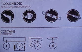
By Gary Boutin

Parts and Supplies:
Ceiling fan used parts

I was doing a job for Janis Bee who lives in Chino, California. She needed my help to install a ceiling fan she purchased at an auction. 

This post shows the seven steps to install a new ceiling fan missing the parts. 

Step 1: Above right Fig.1 shows the fan that Janis purchased at an auction. Below she had taken all the parts out of the box and realized that she was missing most of the parts needed to install the ceiling fan.
Step 2: Fig.2 shows that she tried to install the fan herself. The fan was wired correctly but the fan came with most of the parts missing and no instructions sheet.
Fig.2 Ceiling fan
Step 3: Test each common (white wires), hot (black wires) and green (ground wires) to make sure they are placed correctly into the electrical wire nut (yellow). Now quickly test so see if you have power to the fan motor. The ceiling fan was installed into the ceiling and the exterior cover was installed. 
Step 4: Fig.3 shows where the ceiling fan blades will be attached. The problem was the box did was missing all the fan blade screws. Janis still had the old ceiling fan in her trash can that she had removed earlier and replaced with new unit. Cannibalizing the fan blade screws and rubber fan gasket from the old unit and inserting them into the new fan worked perfectly. There was enough screws to install all four blades. The old screws were dull bronze in color but they had a slip washer and worked fine for securing the blades.
Fig.3 Missing fan blade screws
Step 5: Fig.4 shows the blades are now secured. Later Janis was going to paint the bronze screws with white fingernail polish and it should work since fingernail polish is made with lacquer.
Fig.4 Fan blade screws installed
Step 6: Fig.5 shows the control switch pull for the lamp. These chains was also missing from this box. Janis purchased this white pull at The Home Depot for a few dollars.
Fig.5 Switch pull
Step 7: Fig.6 shows the ceiling fan is complete and works fine. This job is finished.
Fig.6 Job finished

Update: DIY Advisor has New blogs check them today:

  • Cookie Alert: European Union laws requires that you know that this blog uses cookies. If you are concerned about this please click here to see how Google uses this information.

Note: The DIY Advisor assumes no liability for omissions, errors or the outcome of any jobs. The reader must always exercise reasonable caution, follow current codes and regulations that may apply, and is urged to consult with a licensed contractor if in doubt about any steps on these posts. All names were changed to protect client's privacy. DIY Advisor. Reproduction of site content including photos without permission prohibited. All rights reserved. © Copyright 2011-

Wednesday, September 18, 2013

How to Install a Kitchen Gallery Shelf Unit

Mural shelf unit
By Gary Boutin

Parts and Supplies:  
Electric drill 
Gallery shelf kit and instructions
Level  
Screwdriver
Tape measure

Michael works for a program called Uncommon Good that teaches students about green energy. His home is located in Upland, California, a beautiful neighborhood with mature trees in a rural setting. He had just purchased a century-old home and wanted to preserve its look. Being a principal member of Uncommon Good, he was using the house to teach others how to go green. He called my repair service to install a kitchen shelf.

This post shows the ten steps to assemble and install a wooden shelf above the kitchen range. 

Step 1: Fig.1 shows the picture on the box. It shows that the shelf is 23 inches long and it's white.
Fig.1 Gallery shelf kit
Step 2: Fig.2 shows the tools needed for this job. An electric drill, a tape measure, a level and a screwdriver. The bottom  of the box also shows a visual representation of what parts are inside this box.
Fig.2 Tools needed
Step 3: Fig.3 shows the instructions on how to assemble this shelf unit.
Fig.3 The directions
Step 4: Fig.4 shows this part of the box sent a phone number if the directions or if there are missing parts. 1-800-582-7021
Fig.4 Phone number
Step 5: Fig.5 shows the hardware package filled with wood plugs, plastic anchors and metal screws.
Fig.5 Hardware
Step 6: Fig.6 shows the first side of the shelf with two wood plugs inserted into the pre-drilled holes. These wood plugs will hold the base shelf.
Fig.6 Plugs
Step 7: Fig.7 through fig.9 shows the progression on placing the metal screw into the wall. Use the measuring tape to get the exact location. Fig.7 shows the marks on the wall from measuring the exact location of each screw that will hold the shelf. Fig.8 shows a cordless screwdriver placing a metal screw into a plastic wall anchor. Fig.9 shows the exact measurement of the metal screw that will hold the wood shelf and carry all the weight needed. You will need to make two measurement to hold both sides of the shelf.

Fig.7 Measured holes
Fig.8 Cordless screwdriver
Fig.9 The metal screw support
Step 8: Fig.10 shows the pre-drilled screw-slot that will tie onto the screw holding the wood shelf.
Fig.10 Test the screw
Step 9: Fig.11 shows the assembly of the wood shelf, the first leg is on the wall. Fig.12 shows the top shelf is on the legs. Now the shelf is secured and almost ready to use.
Fig.11 Against the wall
Fig.12 Against the wall
Step 10: Fig.13 shows the shelf completed and ready for kitchen herbs and condiments.
Fig.13 All finished

Update: DIY Advisor has New blogs check them today:

  • Cookie Alert: European Union laws requires that you know that this blog uses cookies. If you are concerned about this please click here to see how Google uses this information.

Note: The DIY Advisor assumes no liability for omissions, errors or the outcome of any jobs. The reader must always exercise reasonable caution, follow current codes and regulations that may apply, and is urged to consult with a licensed contractor if in doubt about any steps on these posts. All names were changed to protect client's privacy. DIY Advisor. Reproduction of site content including photos without permission prohibited. All rights reserved. © Copyright 2011-

Monday, September 16, 2013

How to Install Drapery Rods - Part 3 of 3 - Installing Bedroom, Dinning, and Living Room Rods

Fig.1 Puncture the 
plaster with a metal awl
By Gary Boutin

Supplies and Tools:  
Anchors plastic
Awl
Cordless screwdriver with Phillips tip
Drapery wall clip (comes with drapery rods)
Diagonal "Dikes" cutters
Hammer claw 
Metal awl
Scissors 
Tape measure

Michael works for a program called Uncommon Good that teaches students about green energy. His home is located in Upland, California, a beautiful neighborhood with mature trees in a rural setting. He had just purchased a century-old home and wanted to preserve its look. Being a principal member of Uncommon Good, he was using the house to teach others how to go green. He called my repair service to install window dressing.

This post shows fifteen steps to install drapery rods in plaster walls. 

Step 1: Fig.1 shows a metal awl that is marking the holes to be punched. Using the drapery rod clip removes the guess work of where to place the rod clip holes. Fig.2 shows that the metal awl is punched into the plaster walls to widen the hole for the plastic anchor. This step will be repeated until all the holes are marked into the plaster wall. The metal awl resembles a screwdriver but has a sharp, pointed end to make a pointed circular hole into the wall. 
Fig.2 Use the awl to 
make the hole larger
Step 2: Fig.3 shows that a claw hammer is placing the plastic anchor into the plaster walls.
Fig.3 Tap in the plastic anchor
Step 3: Fig.4 and fig.5 shows that the head of the plastic anchor needs to be cut off so that the drapery hook will be flush to the wall. Fig.4 shows diagonal cutter tutting off the head of the wall anchor. Fig.5 shows the head has been cut off so the wall clip will be flush with the wall.
Fig.4 Cut the anchor head off
Fig.5 Diagonal cutters cut the anchor head 
Step 4: Fig.6 shows the drapery wall clip, this one is secured to the wall.
Fig.6 
Drapery clip
Step 5: Fig.7 shows a drapery rod installed over the dining room window.
Fig.7 Drapery rod installed
Step 6: Fig.8 shows a bedroom window with a new drapery rod installed.
Fig.8 Bedroom
Step 7: Fig.9 shows that the curtain must be threaded through before placing the curtain rod on the rod clips.
Fig.9 Blue curtain

Step 8: Fig.10 shows the new blue curtain.
Fig.10 New Curtain
Step 9: Fig.11 shows heavier drapery rods and a rod clip with a flare end.
Fig.11 Drapery rod
Step 10: Fig.12 shows hardware, complete with metal screws, plastic anchor and the metal rod.
Fig.12 Drapery hardware
Step 11: Fig.13 cutting the hardware bag to install the new drapery rods.
Fig.13 Cutting the bag
Step 12: Fig.14 shows the drapery rod installed into the wall ready for the curtain and rod.
Fig.14 Drapery rod hook


Step 13: Fig.15 shows installing the drapery rod into the drapery hook.
Fig.15 Rod install
Step 14: Fig.16 shows drapery rod inserted into rod clip.
Fig.16 Rob secured
Step 15: Fig.17 and fig.18 shows two different draperies placed into the living room windows.
Fig.17 New curtain
Fig.18 Curtains closed
How to Install Drapery Rods:

Update: DIY Advisor has New blogs check them today:

  • Cookie Alert: European Union laws requires that you know that this blog uses cookies. If you are concerned about this please click here to see how Google uses this information.

Note: The DIY Advisor assumes no liability for omissions, errors or the outcome of any jobs. The reader must always exercise reasonable caution, follow current codes and regulations that may apply, and is urged to consult with a licensed contractor if in doubt about any steps on these posts. All names were changed to protect client's privacy. DIY Advisor. Reproduction of site content including photos without permission prohibited. All rights reserved. © Copyright 2011-

G.E. Refrigerator # LSHS6LGZBCSS Water Valve - Part 1 of 4 - Troubleshoot the Problem

Fig.1 G.E. Refrigerator
By Gary Boutin

Part and Supplies:  
Clean Towels
GE Refrigerator LSHS6LGZBCS Manual

Mrs Black has a stainless steel and a white refrigerator in her kitchen. She said she noticed a water puddle near the front of the refrigerator. She called my repair services to have the appliance repaired.

This post shows four steps to troubleshoot the leak.

Step 1: Fig.1 above right shows the a refrigerator that has a possible leak.
Step 2: Fig.2 shows the metal foil placed inside the refrigerator, obtain the model number from the foil. Below is the General Electric foil model number LSHS6LGZBCSS
Fig.2 Metal foil has model number

Step 3: Fig.3 shows the area where the refrigerator lives. The back part has a MDF white molding that had taken on some water and was bloated. There was a sizable leak behind the refrigerator that was cleaned up immediately.
Fig.3 Large water puddle at baseboards.
Step 4: Fig.4 and fig.5 shows the refrigerator is leaking. First, check were the leak comes from. Does it come from the wall or the refrigerator. In this case after picking up the water from the floor and the baseboards, the water was dripping from the bottom of the refrigerator. The next posts will show how to remove the refrigerator backing.
Fig.4 Water puddle

Fig.5 Water coming from the bottom

G.E. Refrigerator Model # LSHS6LGZBCSS Water Valve:
Update: DIY Advisor has three new blogs check them today:

Update: DIY Advisor has three new blogs check them today:
  • Cookie Alert: European Union laws requires that you know that this blog uses cookies. If you are concerned about this please click here to see how Google uses this information.

Note: The DIY Advisor assumes no liability for omissions, errors or the outcome of any jobs. The reader must always exercise reasonable caution, follow current codes and regulations that may apply, and is urged to consult with a licensed contractor if in doubt about any steps on these posts. All names were changed to protect client's privacy. DIY Advisor. Reproduction of site content including photos without permission prohibited. All rights reserved. © Copyright 2011-

Sunday, September 15, 2013

How to Repair Candle Damages on Fireplace Mantle - Part 3 of 3 - Sanding and Painting

Fig.1 1000
grit sandpaper
By Gary Boutin

Supplies and Tools:  
3M 1000 Grit Wet or dry Finishing Paper 
Blue painter's tape
Paint brush
Paint can opener
Paint tray
Paint liner
Paint paddle (free with paint) 
Semi-gloss paint (Sherman Williams) 
Yellow rubber gloves

My home suffered from the holiday cheer. A Christmas candle was left lit and it burned almost past its bottom. The candle thankfully did not burn down the house, but it did damage the white fireplace mantle paint.The surface was left blistered and peeling.

This post shows nine steps to complete sanding and painting the mantle. 

Step 1: Fig.1 shows 3M 1000-Grit Wet or Dry Finishing Paper that will be used to sand the primer paint.
Step 2: Fig.2 shows the sandpaper will be used to sand the primer smooth.
Fig.2 Sanded smooth
Step 3: Fig.3 shows a little paint dust left behind after sanding.
Fig.3 Paint dust
Step 4: Fig.4 and fig.5 shows the dust is picked up by a portable vacuum cleaner.
Fig.4 Vacuum paint
Fig.5 Tape picked up
Step 5: Fig.6 shows the the Sherman Williams semi-gloss paint that will be applied to the area. 
Fig.6 Sherman William paint
Step 6: Fig.7 shows the semi-gloss paint has been stirred into one color. 
Fig.7 Stir the paint
Step 7: Fig.8 shows the final coat of semi-gloss paint being applied to the damaged fireplace mantle.
Fig.8 Final Coat
Step 8: Fig.9 shows the fireplace just needs to have the painter's tape removed.

Fig.9 Fireplace mantle

How to Repair Candle Damages on Fireplace Mantle:

Update: DIY Advisor has New blogs check them today:

  • Cookie Alert: European Union laws requires that you know that this blog uses cookies. If you are concerned about this please click here to see how Google uses this information.

Note: The DIY Advisor assumes no liability for omissions, errors or the outcome of any jobs. The reader must always exercise reasonable caution, follow current codes and regulations that may apply, and is urged to consult with a licensed contractor if in doubt about any steps on these posts. All names were changed to protect client's privacy. DIY Advisor. Reproduction of site content including photos without permission prohibited. All rights reserved. © Copyright 2011-