|
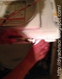
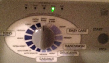
| Fig.1 Bad lamp |
Supplies and Tools:
Drywall 1/2 inch 6 in. in circular pattern
Drywall knives 6 inch
Mud pan
 |
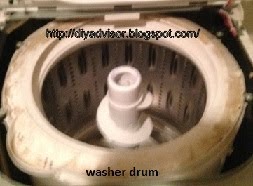
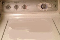
| Fig.2 Ceiling hole |
Tarp grey
Texture Orange-peel
The home owner hired some electricians to add more light into the kitchen. They needed access to the attic and one of them fell on an existing lamp pushing it through the ceiling. They finished the kitchen job but refused to repair the hallway damage. This is a simple job were the light was removed and the ceiling was repaired.
This post shows the six steps to repair a ceiling hole.
Step 1: Fig.1 and fig.2 shows the hole in the ceiling that needs to be repaired. A partial layer of sheet rock was applied but was not flushed with the ceiling.
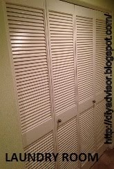
Step 2: Fig.3 shows that a tarp was placed over the rugged floor to prevent joint compound and drywall dust from damaging the floor.
 |
| Fig.3 Tarp the floor |
 |
| Fig.4 Fill the hole |
| Fig.5 Sheetrock sharp razor knife |
 |
| Fig.6 Drywall knife |
 |
| Fig.7 Paper tape |
 |
| Fig.8 Ceiling repaired and drying |
 |
| Fig.9 Spray texture |
 |
| Fig.10 Couple layers of texture |
 |
| Fig.11 Texture finished |
Update: DIY Advisor has New blogs check them today:
- Handyman Blog: DIY Advisor
- DIY Advisor Sitemap
- Food Blog: From Kiwis To Pistachios
- Food Blog Sitemap
- Tool Blog: DIY Advisor Toolbox
- Tool Blog Sitemap
- Artwork Blog: Light in Dark Artwork
- Artwork Blog Sitemap
- Class-A Tests: DIY Class-A Drivers License Tests
- Class-A Tests Sitemap: Class-A Sitemap
- DIY Poem: DIY Poem Meter Blog
- DIY Poem Sitemap: DIY Sitemap
- Cookie Alert: European Union laws requires that you know that this blog uses cookies. If you are concerned about this please click here to see how Google uses this information.
Note: The DIY Advisor assumes no liability for omissions, errors or the outcome of any jobs. The reader must always exercise reasonable caution, follow Current codes and regulations that may apply, and is urged to consult with a licensed contractor if in doubt about any steps on these posts. All names were changed to protect client's privacy. DIY Advisor. Reproduction of site content including photos without permission prohibited. All rights reserved.
© Copyright 2011-