Monday, March 23, 2015

How to Repair a Simple Shutter Latch

Fig.1 Toothpick
By Gary Boutin
 

Supplies and Tools:
Phillip screwdriver
Hex head screwdriver
Hex Head Screw
Toothpick wood

Mr. Georgianna new shutters latch had fallen off and she needed it repaired.

This post shows the four steps to repair a shutter blind.

Step 1: Fig.1 shows a toothpick and a Phillip screwdriver.
Step 2: Fig.2 shows the hex head screw used to tighten the latch.
Fig.2 Blind latch
Step 3: Fig.3 shows that after the toothpick is inserted inside the wall hole, place the existing hex head screw into the existing hole and tighten with a hex head screwdriver.
Fig.3 Blind tightened
Step 4: Fig.4 shows that the job is done until the latch gets loose again.
Fig.4 Job done

Update: DIY Advisor has New blogs check them today:
  • Cookie Alert: European Union laws requires that you know that this blog uses cookies. If you are concerned about this please click here to see how Google uses this information.


Note: The DIY Advisor assumes no liability for omissions, errors or the outcome of any jobs. The reader must always exercise reasonable caution, follow current codes and regulations that may apply, and is urged to consult with a licensed contractor if in doubt about any steps on these posts. All names were changed to protect client's privacy. DIY Advisor. Reproduction of site content including photos without permission prohibited. All rights reserved.© Copyright 2011-

How to Install Two kitchen Knifes Magnetic Bars

Fig.1 New Knife Rack
By Gary Boutin
 

Supplies and Tools: 
Claw hammer
Cordless screwdriver (hand held)
Level
Pencil #2
Phillip bit
Phillip Screwdriver manual
Screws and anchors
Tool rack holder organizer

George Baker is a used car salesman who live in Chino Hills, California. He live in a studio cottage overlooking a golf course overrun by carts and flying golf balls. He had installed a short metal magnetic knife holder in the kitchen but it wasn't large enough to hold all of his kitchen knives.

This post shows the ten steps on how to install an new magnetic organizer bar.

Step 1: Fig.1 shows how the new magnetic bar will look like.
Step 2: Fig.2 shows the tools needed for this job. A claw hammer, a hand held screwdriver with Phillip bit, two screwdriver both Phillip tip.
Fig.2 The installation tools
Step 3: Fig.3 shows the UPC sticker and description for two extra long tool rack holder organizer purchased on the Internet. 
Fig.3 Tool Rack Holder Organizer
Step 4: Fig.4 shows the packaged screws for the organizer. Fig.5 and fig.6 shows the screws and anchors for hanging the organizer bar. This set came with 4-metal screws, but it did not come with wall anchors. Fig.6 shows many types of wall anchors, some plastic and some metal. For this job large plastic wall anchors were used.
Fig.4 Package screws
Fig.5 Many sized wall anchors
Fig.6 Plastic anchors
Step 5: Fig.7 through fig.10 shows the removal of the old magnetic bar. Fig.7 shows the old magnetic bar. Fig.8 through fig.10 shows the steps to remove the bar. The magnetic bar had to be pried apart to remove the front cover. Once the cover was removed the installation screws could be removed. The block of wood was used to give some space between the outside cover and the wall.
Fig.7 Old magnetic knife bar
Fig.8 White magnet gray backing
Fig.9 Magnetic strips
Fig.10 Parts taken apart and stored
Step 6: Fig.11 shows the two magnetic bars that will be installed in the kitchen wall.
Fig.11 Two magnetic bars
Step 7: Fig.12 shows the one magnetic bar over the electrical plug. The magnetic torpedo level is attached to the metal rail to keep it straight. Use a pencil to assist that will be installed in the kitchen wall. It shows were to make the holes in the walls.
Fig.12 Torpedo Level
Step 8: Fig.13 and fig.14 shows to use of a #2 pencil to mark the holes for the magnetic rail. Fig.14 shows the use of a Phillip screwdriver to punch a hole in the wall. This techniques help when using plastic anchors.
Step 13: #2 pencil
Step 14: Phillip screwdriver
Step 9: Fig.15 shows the plastic anchor is placed in the wall. The plastic anchor is a place holder for the metal screws that will hold the metal rail on the wall. Four anchors were used for the knife rail. Use the claw hammer to hammer the plastic anchor flat into the wall. Just pushing the anchor in the wall will not work as well as if a hammer is used.
Step 15: Plastic anchor
Step 10: Fig.16 through fig.18 shows three pictures were the knives were placed on the magnetic organizer.
Fig.16 Left side
Fig.17 Middle
Fig.18 Knife rack color coded

Update: DIY Advisor has New blogs check them today:
  • Cookie Alert: European Union laws requires that you know that this blog uses cookies. If you are concerned about this please click here to see how Google uses this information.


Note: The DIY Advisor assumes no liability for omissions, errors or the outcome of any jobs. The reader must always exercise reasonable caution, follow current codes and regulations that may apply, and is urged to consult with a licensed contractor if in doubt about any steps on these posts. All names were changed to protect client's privacy. DIY Advisor. Reproduction of site content including photos without permission prohibited. All rights reserved. © Copyright 2011-

How to Replace Door Shoe

12 Volt Cordless
By Gary Boutin

Supplies and Tools:  
Cordless screwdriver with Phillip bit Door 
shoe replacement - Brown  
Drill bit 1/4 inch 
Pliers 
Razor knife  
Silicone Seal-Clear 

While visiting a friend from Wrightwood, California we noticed that his door shoe on his pre-hung door needed to be replaced. This is a simple job, but needs to be done every couple of years, if the threshold has direct contact with the door shoe. This door shoe rides on top of the threshold plate and together they serve to keep unwanted dirt and moisture (water) from entering the home. This shoe was worn out and little strands of rubber could be seen from underneath the door and threshold plate. In higher country where moisture could damage the flooring of this home. Its one more maintenance item that needs to be addressed when noticed.

This post shows the nine steps on how to remove a door shoe on a pre-hung door.  

Step 1: Fig.1 shows the damaged door shoe being slipped off.  
Fig.1 Door shoe
Step 2: Fig.2 shows before the door shoe is removed the door spring stop needs to be taken off the door. Fig.3 shows that grabbing the door spring with one hand and twist left. Completely removed the spring from stop shoe and remove the screw in the middle of the stop.
Fig.2 Grab the spring
Fig.3 Spring removed
Step 3Fig.4
shows a cordless screwdriver with Phillip bit removing metal pan head screws from the older door shoe. When this door shoe was placed it was in the middle of winter, the door shoe kit came with small button Phillip screws, we decided to use pan head screws to give the shoe a large and more secured attachment to the door.
Fig.4 Remove screws
Step 4Fig.5
shows a razor knife to remove the seal at the edge of the door shoe and the door. At both side of the door is the top part of the door shoe.  

Fig.5 Razor knife
Step 5
Fig.6
shows that the plastic door shoe (above top right) is being pulled off the bottom of the metal door. Fig.7 shows the bottom of the door without the door shoe in place. Fig.8 shows the dirt and water at the bottom of the door shoe which meant the door seal was broken and the water went inside the door seal. In this case it didn't matter because the door was made of metal but some doors are made of wood and then it would mater because the water would be absorbed into the door.

Fig.6 Shoe pulled off
Fig.7 No shoe on door
Fig.8 Dirt and water


Step 6Fig.9 shows the pan head screws being replaced after a new door shoes was being replaced. The edges are so tight that the door shoe itself mold itself to the new door.
Fig.9 Screws being placed
Step 7Fig.10 shows after the door shoe is in place the door spring is the last part to be placed.
Fig.10 Door spring stop
Step 8Fig.11 shows another screw was placed by the door spring. A clear silicone seal was placed above the door edge.
Fig.11 Spring Screw

Step 9Fig.12 shows the job is finished.
Fig.12 Door shoe installed

Update: DIY Advisor has New blogs check them today:
  • Cookie Alert: European Union laws requires that you know that this blog uses cookies. If you are concerned about this please click here to see how Google uses this information.


Note: The DIY Advisor assumes no liability for omissions, errors or the outcome of any jobs. The reader must always exercise reasonable caution, follow current codes and regulations that may apply, and is urged to consult with a licensed contractor if in doubt about any steps on these posts. All names were changed to protect client's privacy. DIY Advisor. Reproduction of site content including photos without permission prohibited. All rights reserved. © Copyright 2011-

How to Make a Commercial Signage

Fig.1 The parts
By Gary Boutin

Supplies and Tools:
Advertisement board 2 ft. x 4 ft.
Concrete pier block 8-3/4 in. x 10-3/4 in. x 10-3/4 in.
Cordless drill with 1/8 inch drill bit
Claw hammer 
Drill bit 1/8 inch
Fender washers (4) 
Hand staple with 1/4 inch staples
Lag bolts (4) 
Open and closed end wrench 1/4 inch
Post - Douglas Fir 4 x 4 x 8
Metal tie 4-In. by 4-In. Simpson strong tie
Sheetrock screws 1-1/4 inch
Torpedo level magnetic

This project was put together because the Lumber/Building Materials needed a sign to sell insulation. 

This post explains how to make a simple post advertisement that can be used in many application. This sign is used inside a warehouse store, but it can also be adapted to be used at garage sales and parties.

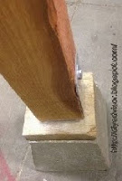
Step 1: Fig.1 shows some of the parts used in this project. 4-lag screws, 4-fender washers and 1-concrete pier block.
Step 2: Fig.2 shows the advertisement sign, 4x4x8 Douglas Fir post, Simpson tie metal post bracket on top of a orange Home Depot Cart.
Fig.2 cart with parts
Step 3: Fig.3 shows the tools on top of The Home Depot cart. Cordless drill with drill bit 1/8 inch, claw hammer, closed-end wrench 1/4 inch, torpedo level and crescent wrench. Fig.4 shows that a lag screw with a fender washer (Oversize Washer) being screwed into the concrete pier and attaching the Simpson metal tie in place. Two lag screws were used to secure the tie to the concrete pier.
Fig.3 Cart with tools
Fig.4 Closed-end wrench
Step 4: Fig.5 shows a torpedo level leveling the wood post to the Simpson metal tie.
Fig.5 Torpedo leveling
the wood post
Step 5: Fig.6 and fig.7 shows a Lag Screw being screwed into the post. Fig.7 shows that a socket wrench with a 1/4 inch socket is being used to drive the lag screw in place. One lag screw per side and a total of two lag screws were used to secure the wood post to the Simpson metal tie.
Fig.6 Lag screw
Fig.7 Socket Wrench

Step 6: Fig.8 and fig.9 shows that one this side is secured, and the post is ready to receive its advertisement board. Fig.9 shows a top view of the secured post.
Fig.8 This side finished
Fig.9 Top view
Step 7: Fig.10 and fig.11 shows that the post was laid on top of a flat cart. This is the easiest way to attach the 2 by 4 foot advertisement board. 
Fig.10 Laying the post
Fig.11 Positioning the post
Step 8: Fig.12 shows the advertisement board is attached with sheetrock Screws 1-1/4 is just fine.  Create a paper sign and use a hand stapler to attache the sign to the wood board. Fig.13 shows the signage in place advertising interior fiberglass.
Fig.12 Ad board
Fig.13 Job done

Update: DIY Advisor has New blogs check them today:
  • Cookie Alert: European Union laws requires that you know that this blog uses cookies. If you are concerned about this please click here to see how Google uses this information.

Note: The DIY Advisor assumes no liability for omissions, errors or the outcome of any jobs. The reader must always exercise reasonable caution, follow current codes and regulations that may apply, and is urged to consult with a licensed contractor if in doubt about any steps on these posts. All names were changed to protect client's privacy.  Reproduction of site content including photos without permission prohibited. All rights reserved. © Copyright 2011-