Showing posts with label cordless drill. Show all posts

Sunday, April 5, 2015

How to Install Custom White Aluminum Door - Part 3 of 3 - Hardware Installation

Electric drill 120-volt
By Gary Boutin
 
Supplies and Tools: 
Complete door hardware directions
Handle guard template (Black with 3-holes) 
Drill bits 1/8 inch, 3/32 inch 
Electric drill cordless and 120 Volt
Glasses safety 
Pencil #2  
Screwdriver flat tipped
Screwdriver Phillip tip
Tape measure 

On Easter Sunday, we celebrate the resurrection of the Lord, Jesus Christ. This Easter it seams appropriate to show how to finish the installation a custom entomology (insects) screen. Easter in many regions of our valley is were the no see-em bugs come out. We are all looking forward to our local insects that will stalked us in April. Mr. Gonzales was a truck driver for a local dairy company and he was moving to Chino Valley Senior Apartment Complex. He needed this job done since he could no longer handle any tools. 

This post shows the eleven steps on how to install the door hardware on a screen door.  

Step 1: Fig.1 shows the complete directions for installing a new hardware for this screen door.
Fig.1 The hardware plans
Step 2: Fig.2 shows the new location of the door handle. It also shows the door handle guard template on the outside of the door. This template assures the drilled holes will be at their correct height and location for the aluminum door.  
Fig.2 Door template is 
located just above 
the door handle
Step 3: Fig.3 shows the handle guard template on the inside of the door and the center hole is drilled.
Fig.3 Template

Step 4: Fig.4 shows the top hole is being drilled. Fig.5 shows the drill is holding the handle guard template in place fore the bottom hole to be drilled. 
Fig.4 Top hole
Fig.5 Bottom hole
Step 5: Fig.6 and fig.7 shows the door holes are drilled again to remove any sharp edges from the door handle.
Fig.6 Removing 
sharp edges
Fig.7 Plastic handle 
ready to install
Step 6: Fig.8 shows the door handle with the direction on the background. Fig.9 shows the installation of the handle and being tightened with Phillip screws.
Fig.8 Door handle
Fig.9 Handle ready
Step 7: Fig.10 and fig.11 shows the final adjustment to the door screen handle.
Fig.10 Fine tuning
Fig.11 Outside handle
Step 8: Fig.12 shows the door handle latch template and fig.13 shows the template will be placed on the door frame for the exact location of the door latch.
Fig.12 Paper template
Fig.13 Template on wood frame
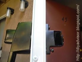
Step 9: Fig.14 shows the last screw being placed on the bottom of the door latch.
Fig.14 Latch done
Step 10: Fig.15 shows the door closer plans and fig.16 shows the actual parts on the door closer is attached to the door frame.
Fig.15 Door closer plans
Fig.16 Door closer
Step 11: Fig.17 shows the door screen is completely installed.
This job is done and Mr. Gonzales can invite his family for the holidays.
Fig.17 Job done
 How To Install a Custom White Aluminum Door:

Update: DIY Advisor has New blogs check them today:
  • Cookie Alert: European Union laws requires that you know that this blog uses cookies. If you are concerned about this please click here to see how Google uses this information.


Note: The DIY Advisor assumes no liability for omissions, errors or the outcome of any jobs. The reader must always exercise reasonable caution, follow current codes and regulations that may apply, and is urged to consult with a licensed contractor if in doubt about any steps on these posts. All names were changed to protect client's privacy. DIY Advisor. Reproduction of site content including photos without permission prohibited. All rights reserved. © Copyright 2011-

How to Install Custom White Aluminum Door - Part 2 of 3 - Door Screen Alignment

Fig.1 Aviation shears
By Gary Boutin 
  
Supplies and Tools: 
Aviation snips
Claw hammer
Cordless drill driver
Drill bits 1/8 inch, 3/32 inch
Electric drill 
File metal
Glasses safety
Hacksaw (32 teeth per inch)
Pan head screws self drilling
Pencil #2 Carpenter style
Screwdriver flat tipped
Screwdriver Phillip tip
Tape measure
Wood chisels
Wood door shims

On Easter Sunday, Christians celebrate the resurrection of the Lord, Jesus Christ. This Easter it seams appropriate to show how to install a custom bug screen. Easter in many regions of the California is when the large bugs and no see-em bugs come out. That's what we have to look forward to in April. Mr. Gonzales moved to a converted apartment turned into a Senior Apartment Condominium Complex for senior citizen. He wanted a flashy front screen door and he purchase his custom door from a Lowe's.

This post shows the twelve steps on how to align and install the door. 

Step 1: After reading the directions, the next step is to remove all the parts from the box and make sure all the hardware parts are enclosed. Above right fig.1 shows aviation snips that was used to cut down the aluminum door trim. 
Step 2: Fig.3 shows a cordless drill driver and a 1/8 inch drill bit drilling pilot starter holes for the Hinge Side Frame.
Fig.3 Starter holes

Step 3: The inside door jamb trim wasn't flat, and it was flared away from the front door so wooden shims were used to keep the jamb flat. Fig.4 and fig.5 shows wood door shims placed on the edge of the door jamb for the top and bottom hinge.
Fig.4 Top door hinge
Fig.5 Bottom door hinge
Step 4: Fig.6 and fig.7 shows a torpedo level is being used to make sure the screen door frame is straight and level. The torpedo level has a glass tube with a bubble in the middle to indicate it is level. Level in this case means the hinge side frame is aligned to the existing door frame and straight.
Fig.6 Torpedo level
Fig.7 Level the bubble 
is in the middle
Step 5: Fig.8 and fig.9 shows the bottom edge of the door is placed inside of the hinge side frame and pushed inside and upwards until the door is aligned inside the hinge side frame. 
Fig.8 Installing door
Fig.9 Aligning door
Step 6: Fig.10 shows the top edge of the door inside the hinge side frame. Now what needs to be done is secure the door to the hinge side frame with metal screws.

Fig.10 Top door edge 
aligned with hinge frame
Step 7: Fig.11 shows that a cordless screwdriver drilling a pilot hole into the door and hinge side frame. Fig.12 shows a cordless screwdriver placing self drilling pan head screws into the aluminum frame. Fig.13 shows a pan head screw has been inserted into the door.
Fig.11 Drilling into 
frame and door
Fig.12 Measure door and
 install pan head screws
Fig.13 Pan head 
screws installed
Step 8: Fig.14 shows the upper top right of the screen door is within the door jamb.
Fig.14 Right top of door
Step 9: Fig.15 shows the right side of the door is within the latch door frame.
Fig.15 Door alignment
Step 10: Fig.16 shows the bottom plate is flush to the door frame. Fig.17 shows the metal edge is cutting into the wood jamb the bottom plate is too long. Fig.18 and fig.19 shows the use aviation snips to cut a notch into the base plate so only the door edge touches the wood jamb. Use a metal file to make sure the metal edges are not razor sharp.
Fig.16 Bottom plate
Fig.17 Edge too long
Fig.18 Notching the edge
Fig.19 Using metal shears to 
cutting bottom plate
Step 11: Fig.20 and fig.21 shows the bottom plate is attached facing the right side of the door. Use of wood chisels helped get the bottom plate in position for securing the plate to the door
Fig.20 Wood chisel help 
adjust bottom door shield
Fig.21 Pencil edge 
for bottom plate

Step 12: Fig.22 shows the cordless screwdriver drilling a hole through the bottom of the hinge side frame. Fig.23 shows a hole was drilled but not through the screen door. Fig.24 shows a self drilling pan head screw was used to drill into the screen door to secure the hinge frame and the screen door.
Fig.22 Ryobi cordless 
drilled bottom hole
Fig.23 Hole drilled covering door
Fig.24 Inserted pan head screw
How To Install a Custom White Aluminum Door:


Update: DIY Advisor has New blogs check them today:
  • Cookie Alert: European Union laws requires that you know that this blog uses cookies. If you are concerned about this please click here to see how Google uses this information.


Note: The DIY Advisor assumes no liability for omissions, errors or the outcome of any jobs. The reader must always exercise reasonable caution, follow current codes and regulations that may apply, and is urged to consult with a licensed contractor if in doubt about any steps on these posts. All names were changed to protect client's privacy. DIY Advisor. Reproduction of site content including photos without permission prohibited. All rights reserved. © Copyright 2011-

Monday, March 23, 2015

How to Make a Commercial Signage

Fig.1 The parts
By Gary Boutin

Supplies and Tools:
Advertisement board 2 ft. x 4 ft.
Concrete pier block 8-3/4 in. x 10-3/4 in. x 10-3/4 in.
Cordless drill with 1/8 inch drill bit
Claw hammer 
Drill bit 1/8 inch
Fender washers (4) 
Hand staple with 1/4 inch staples
Lag bolts (4) 
Open and closed end wrench 1/4 inch
Post - Douglas Fir 4 x 4 x 8
Metal tie 4-In. by 4-In. Simpson strong tie
Sheetrock screws 1-1/4 inch
Torpedo level magnetic

This project was put together because the Lumber/Building Materials needed a sign to sell insulation. 

This post explains how to make a simple post advertisement that can be used in many application. This sign is used inside a warehouse store, but it can also be adapted to be used at garage sales and parties.

Step 1: Fig.1 shows some of the parts used in this project. 4-lag screws, 4-fender washers and 1-concrete pier block.
Step 2: Fig.2 shows the advertisement sign, 4x4x8 Douglas Fir post, Simpson tie metal post bracket on top of a orange Home Depot Cart.
Fig.2 cart with parts
Step 3: Fig.3 shows the tools on top of The Home Depot cart. Cordless drill with drill bit 1/8 inch, claw hammer, closed-end wrench 1/4 inch, torpedo level and crescent wrench. Fig.4 shows that a lag screw with a fender washer (Oversize Washer) being screwed into the concrete pier and attaching the Simpson metal tie in place. Two lag screws were used to secure the tie to the concrete pier.
Fig.3 Cart with tools
Fig.4 Closed-end wrench
Step 4: Fig.5 shows a torpedo level leveling the wood post to the Simpson metal tie.
Fig.5 Torpedo leveling
the wood post
Step 5: Fig.6 and fig.7 shows a Lag Screw being screwed into the post. Fig.7 shows that a socket wrench with a 1/4 inch socket is being used to drive the lag screw in place. One lag screw per side and a total of two lag screws were used to secure the wood post to the Simpson metal tie.
Fig.6 Lag screw
Fig.7 Socket Wrench

Step 6: Fig.8 and fig.9 shows that one this side is secured, and the post is ready to receive its advertisement board. Fig.9 shows a top view of the secured post.
Fig.8 This side finished
Fig.9 Top view
Step 7: Fig.10 and fig.11 shows that the post was laid on top of a flat cart. This is the easiest way to attach the 2 by 4 foot advertisement board. 
Fig.10 Laying the post
Fig.11 Positioning the post
Step 8: Fig.12 shows the advertisement board is attached with sheetrock Screws 1-1/4 is just fine.  Create a paper sign and use a hand stapler to attache the sign to the wood board. Fig.13 shows the signage in place advertising interior fiberglass.
Fig.12 Ad board
Fig.13 Job done

Update: DIY Advisor has New blogs check them today:
  • Cookie Alert: European Union laws requires that you know that this blog uses cookies. If you are concerned about this please click here to see how Google uses this information.

Note: The DIY Advisor assumes no liability for omissions, errors or the outcome of any jobs. The reader must always exercise reasonable caution, follow current codes and regulations that may apply, and is urged to consult with a licensed contractor if in doubt about any steps on these posts. All names were changed to protect client's privacy.  Reproduction of site content including photos without permission prohibited. All rights reserved. © Copyright 2011-