Showing posts with label needlenose pliers. Show all posts

Saturday, September 17, 2016

How to Repair a Cooling Fan - Part 3 of 3 - Closing and Finishing

This picture shows the ThreeLeaf Logo
ThreeLeaf Logo
By Gary Boutin

Tools and Supply:
Clear Silicone
Metal foil tape
Needlenose pliers
Wire Nuts


We purchase two ThreeLeaf T102 - Laptop Cooling Pad for $12.99 each and one lasted one day, and the other lasted two months. The weak part of the fan was its power cable which could easily be yanked out of the fan. 

This post shows the four steps to secure the cooling fan power cable and close the top of the unit.

Step 1: Fig.1 above is the TreeLeaf Logo. Fig.2 below shows that the first steps was to secure the wire nuts to the plastic case using white silicone caulking. The caulking is white but will be clear when it dries.

This picture shows both wire nuts caulked together
Fig.2 Wire nuts caulked

Step 2: Fig.3 shows the wiring from each fan was caulked with silicone to make sure they do not move. 
Apply silicone to fan wiring in the middle of the cooling fan
Fig.3 Fan wires caulked

Step 3: Fig.4 shows that even though the wire nuts and the fan wiring was caulked with silicone. The lead wire was additionally caulked to the plastic case. Notice the white on the back of the case.
Added silicone to front lip of cooling fan
Fig.4 More caulking
Step 4: Fig.5 shows another layer of protection was added to make sure the power lead wire would not be pulled off the case. Fig.6 shows the power was checked prior to assembly. Fig.7 shows the cooling fan was working and powered from the HP laptop. Use needlenose pliers to straighten all the metal tabs, and place the grill into the plastic case. Now, use the flat tip screwdriver to bed down the metal tabs and this will secure the unit for use. This end these cooling repair post.
Added metal foil tape to the front of the unit
Fig.5 Metal Foil Tape
Plugged cooling fan into laptop and it runs fine
Fig.6 Power is working
Cooling fan repaired
Fig.7 Assembled

How to Repair a Cooling Fan:


  • Cookie Alert: European Union laws requires that you know that this blog uses cookies. If you are concerned about this please click here to see how Google uses this information.

Note: The DIY Advisor assumes no liability for omissions, errors or the outcome of any jobs. The reader must always exercise reasonable caution, follow current codes and regulations that may apply, and is urged to consult with a licensed contractor if in doubt about any steps on these posts. All names were changed to protect client's privacy. DIY Advisor. Reproduction of site content including photos without permission prohibited. All rights reserved. © Copyright 2011-

Saturday, September 3, 2016

Peep Hole - Part 2 of 6 - The Tools

Fig.1 Crescent Wrench
By Gary Boutin

Supplies and Tools:
Hole Saw Kit
Fig.2 Open/closed-End Wrench
Needlenose pliers
Ruler
Screwdriver (flat tipped)
Vice Grips® pliers


Mrs. Black wanted a better security peep hole on her front door. These post shows the tools process. 

This post shows seven steps on what tools needed for this job.

Step 1: Fig.3 shows below are the tools needed for the job. The list is on the upper left of this posts. Ideally an open end wrench is better than needlenose  pliers to secure the nut.  The ruler and the hole saw kit is to make sure that the size of 1-3/4 hole saw is used for the opening of the new large hole.
Fig.3 Ruler and Hole Saw
Step 2: Fig.4 shows the tools below are Vice Grips®, and Needlenose pliers. It would have been better if a Crescent Wrench with open/closed-end wrench that way there is no slippage. But those tools were in another tool box away from the work site.

Fig.4 Tools to secure hole saw
Step 3: Fig.5 shows any Hole Saw Kit will work, it does not have to be a name brand. But if that is what you have in your tool chest, use it. Fig.6 shows a 1-3/4 inch saw hole saw assembled and ready to cut the door hole.

Fig.5 Hole Saw Kit
Fig.6 Hole 1-3/4 inch saw
Step 4: Fig.7 shows the wrong tools are used to secure the hole saw to the base. The next post is the new peep hole called Giant Screen. At the top of the post on the right side shows fig.1 crescent wrench and fig.2 shows open end wrench. Those are the correct tools to secure this hole saw.
Fig.7

Step 5: Fig.8 are the Prime-Line drilling directions for U 9917 Giant Screen Viewer:
Fig.8 Prime-Line Drilling Directions

Step 6: Drills: Fig.9 is the pilot hole if the door does not have an existing peep hole. Fig.10 - 3/16 for the pilot hole that the hole saw drill bit will be used in combination with this hole.
Fig.9 - 3/32 Wood Drill for a new hole
Fig.10 - 3/16 Wood Drill
Step 7: Fig.11 shows caulking is not necessary, but if the home is in an area that rains then purchase clear silicone.
Fig.11 Caulking the sides


Peep Hole Series Below:


  • Cookie Alert: European Union laws requires that you know that this blog uses cookies. If you are concerned about this please click here to see how Google uses this information.

Note: The DIY Advisor assumes no liability for omissions, errors or the outcome of any jobs. The reader must always exercise reasonable caution, follow current codes and regulations that may apply, and is urged to consult with a licensed contractor if in doubt about any steps on these posts. All names were changed to protect client's privacy. DIY Advisor. Reproduction of site content including photos without permission prohibited. All rights reserved. © Copyright 2011-

Saturday, January 2, 2016

How to Create and Install Xenon Pucks into a Bedroom Light Tier - Part 6 of 8 - Cutting the Xenon Plug Hole

Fig.1 Commercial 
Electric® 
Xenon Lamp Kit
By Gary Boutin 

Supplies and Tools:
#8 Wood screws 
18-Volt Ryobi Cordless Phillip Screwdriver
Claw hammer (small)
Commercial Electric® 3 Light Xenon Task Kit
Electrical tape (black)
Galvanized flat sheet metal (36 in by 48 in)
Jewelers Precision Screwdriver Set
Marking pen (any color)
Metal files
Metal Hole saw kit
Needlenose pliers
Spring clips small (green)

In 1991 we received a bed set with a light tier over the bed. It had side drawers tiers tall enough to hold over the mirror a bridge that housed 3-incandescent lights that could be dimmable from a switch within the headboard. Theses posts shows my solution. 

This post shows eight steps to installing the Commercial Electric® puck lights

Step 1:
Fig.1 and fig.2 shows the Commercial Electric® 3 Light Xenon Task and Accent Light Kit.
Fig.2 Open the Kit

Step 2: Fig.3 shows the puck Commercial Electric® Xenon® light that will be installed on the old lamp.
Fig.3 Xenon light

Step 3: Fig.4 and fig.5 shows that using a permanent marker will mark the area to be cut.
Fig.4 Marker

Fig.5 Place in the middle

Step 4: Fig.6 shows the outer edges of the Commercial Electric® Xenon® lamp makes a perfect template to cut.
Fig.6 The Template

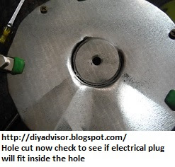
Step 5: Fig.7 shows to place the Commercial Electric® Xenon plug into the size of the hole saw to make sure it fit correctly. Fig.8 shows the needlepoint vice grip® pliers and Ryobi cordless drill with a hole saw to cut into the base of the lamp. Fig.9 shows that using a claw hammer to knock down the sheet metal that was cut from the hole saw.
Fig.7 Puck plug

Fig.8 Cutting the lamp

Fig.9 Claw hammer

Step 6: Fig.10 and fig.11 shows the hardware screws organizer.
Fig.10 Hardware
Fig.11 Wood screws

Step 7: Fig.12 shows that using the same hole saw to cut through the sheet metal. Fig.13 and fig.14 shows the sheet metal is cut and there is enough metal to push through the metal base.
Fig.12 Sheet metal

Fig.13
Fig.14 Push hole through
Step 8: Fig.15 and fig.16 shows the electrical wiring plug fits through hole.
Fig.15

Fig.16 Lamp sealed
with electrical tape


How to Create and Install Xenon Pucks into a Bedroom Light Tier


Update: DIY Advisor has New blogs check them today:

  • Cookie Alert: European Union laws requires that you know that this blog uses cookies. If you are concerned about this please click here to see how Google uses this information.

Note: The DIY Advisor assumes no liability for omissions, errors or the outcome of any jobs. The reader must always exercise reasonable caution, follow current codes and regulations that may apply, and is urged to consult with a licensed contractor if in doubt about any steps on these posts. All names were changed to protect client's privacy. DIY Advisor. Reproduction of site content including photos without permission prohibited. All rights reserved. © Copyright 2011-

Tuesday, April 21, 2015

How to Replace 2005 Lincoln LS Brake Console Switch

Fig.1 Ford 2005 Lincoln
LS automobile
By Gary Boutin
 
Supplies and Tools:
Brake console switch - $30
Electrical Star screwdriver (black handle)
Electrical stripper (Yellow handles)
Electrical tape
Pliers standard (Orange handles) 
Needlenose pliers
Putty scraper
Vicegrip® pliers 

Mrs. Stone drives a Ford 2005 Lincoln LS automobile pictured right top of this page. While at the car wash a worker pushed in the brake console switch inside the interior console. This post shows how to replace this part. 

This post shows the ten steps on how to repair 2005 Lincoln LS Brake Console Switch Replacement.
Step 1: Fig.1 shows a Ford 2005 Lincoln LS automobile.
Step 2: Fig.2 shows the tools; Phillip screwdriver, Electrical Stripper, Pliers (standard), Needlenose pliers, Putty Scraper and Vicegrips® Pliers.
Fig.2 Tools for this job
Step 3: Fig.3 shows the coffee cup tray console that housed the brake handle, brake light switch (dark rectangular hole bottom left) and two side by side traveling coffee holders. The bottom black rectangle is the area of interest for this post. Use the putty scraper in combination with a flat end screwdriver in fig.1 to removed the console cover by prying the edges and pull outwards. Pull slowly because the cover has two switches attached to the back portion. In this case only one the brake handle was attached. 
Fig.3 Console cover tray
Step 4: Fig.4 shows the cover removed and interior electrical wires. The black brake switch bottom of the picture is the switch that needs to be replaced. When the brake switch was pushed down the mounting plate was broken off so the switch had to be replaced.
Fig.4 inside console
Step 5: Fig.5 shows an upside down coffee cup tray, the rectangle in the bottom of this picture is were the switch is suppose to be. Try to push the tray to the side so you can reach the electrical wiring.
Fig.5 Underneath 
coffee tray
Step 6: Fig.6 shows the hand brake cable. There is no need to remove this but it does give more room to get to the electrical wiring.
Fig.6 Brake cable
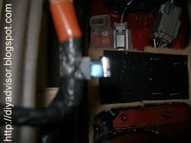
Step 7: Fig.7 shows the black electrical tape that will need to be removed to get to the electrical junction. Sometimes the wires at the back of the switch can be pulled off and replaced on the new switch. But in this case the wires were part of the switch.
Fig.7 Wire junction
Step 8: Fig.8 shows that the black electrical tape was removed revealing the junction between the brake switch and the orange power line. Pull the lines apart and release it from the orange cable. Use a razor knife to remove the black electrical tape and to reapply the tape back on the new switch wiring. Electrical stripper were used to remove the existing wiring and to place the new switch wiring.

Note: Remember how electrical junction was removed because the new switch will need to be put back on.
Fig.8 Tape removed
Step 9: Fig.9 shows the removal and replacement of the brake switch using a Star Screwdriver. Remove or replace take two screws from the new brake light switch
Fig.9 New brake light switch
Step 10: Fig.10 shows both switches are ready to be placed into the console.
Fig.10 New switch 
and cable installed
Step 11: Fig.11 and fig.12 shows the cover being placed back into the center console. Install in reverse order of the removal.
Fig.11 Tap both sides 
of console lid
Fig.12 Pushing lid in place

Lincoln LS E-books:

Update: DIY Advisor has New blogs check them today:
  • Cookie Alert: European Union laws requires that you know that this blog uses cookies. If you are concerned about this please click here to see how Google uses this information.


Note: The DIY Advisor assumes no liability for omissions, errors or the outcome of any jobs. The reader must always exercise reasonable caution, follow current codes and regulations that may apply, and is urged to consult with a licensed contractor if in doubt about any steps on these posts. All names were changed to protect client's privacy. DIY Advisor. Reproduction of site content including photos without permission prohibited. All rights reserved. © Copyright 2011