Showing posts with label screws. Show all posts

Monday, October 19, 2015

How to Install Plastic Outer Corner Gutter

Fig.1 The job
By Gary Boutin

Tools and Supplies:
Circular saw 5 1/4 inch blade
Caulking gun, Caulking latex
Cordless screwdrivers

Knife flat
BEHR Premium Plus Ultra
Fig.2 Finished 
gutter system
Paint brush
Propane tank with striker
Screws 4-inch
Tape measure
Wood block 2x6 Douglas Fir

Wood glue 

Amerimax Home Products Supplies:  

Traditional Vinyl Gutter 10 ft. Brown
Vinyl K-Style Joiner 10 ft. Brown
Vinyl Hidden Hangar Brown
Outside corner Brown  
Downspout plastic clips Brown 
Drop outlet 2 in. x 3 in. Brown 
Vinyl Gutter gutter silicone - Clear

Mr. Jones had done most of the job of installing Amerimax Home Products vinyl gutters that he purchased from The Home Depot. He had pulled his back on the final corner and was not able to finish the job. He hired my service to finish the work. Fig.1 above shows the work that needs to be done and it's the last corner before the job was finished. Fig.2 shows the work that was done and fig.3 shows a side view that the gutter need to be cut and fitted into the outer corner. But the real problem was Mr. Jones wanted gutter placed on a side of the house that gutters are not placed. His reasoning was that when it rained a sheet of water fell over that side of the roof.

This post shows the seven steps on how the outer corner was installed and how we solved the problem of having two different heights. The roof was not the same heights as the garage roof line. Thus we could not attach them together. A drop outlet was installed on the higher gutter so when the rain water flows off the roof it could be contained inside the vinyl gutter system. 

Step 1: Cutting the gutter to fit the outer corner and fig.4 shows the side of the house that will need to have a gutter placed. 
Fig.3 Side view of 
corners repair
Fig.4 Two different 
roof fascia
Step 2: Fig.5 shows how the gutter ends was cut to fit the new outer corner. Use a hot knife and push the knife through the plastic gutter. 
Fig.5 Hot knife


Step 3: Outside corner installed. Fig.6 shows the outside corner is being adjusted. Fig.7 shows the dry fit of the outside corner into the existing gutter. Fig.8 shows that a tape measure was used to measure the edge to finish the job. After the gutter was cut, insert the outside corner in place and use deck screws to place it against the existing wood fascia. Once the corner is inserted measure the next part of the gutter and install it. Fig.9 shows to use brown plastic joins to secure the ends. Once the piece is correct place use clear silicone inside the corner.
Fig.6 fitting corner 
with joins
Fig.7 Corner being inserted
Fig.8 Last gutter piece 
measured
Fig.9 Corner being 
supported with joiner
Step 4: Wood edge attached to roof fascia. Fig.10 through fig.12 shows the making of an wood support to help hold the gutter system. Fig.11 and fig.12 shows the triangular edge was cut using a circular saw from a 2x6 Douglas Fir and glued to the existing fascia edge. Holes were drilled into the wood support to house four metal 4-inch screws into the edge of the support piece. A cordless screwdriver was used to insert the screws into the support piece.
Fig.10 Measured
Fig.11 Measure triangle
Fig.12 Cut the piece
Step 5: Wood roof edge painted brown. Fig.13 through fig.15 shows the support will be behind the vinyl gutter and thus needed to be painted. Using a paint brush we chose BEHR Premium Plus Ultra to protect the wood piece behind the gutter. The paint doesn't match but it wont be seen behind the gutter.
Fig.13 Prime 
and paint brown
Fig.14 Insert metal screws
Fig.15 Paint the inside too

Step 6: Fig.16 through fig.18 shows the gutter was cut and placed into the downspout. This was not level because it would go over the top of the existing garage gutter. Fig.18 shows the gutter is being measured past the downspout to add additional gutter to the end. Use a cordless drivers to insert screws from the gutter into the wood fascia.
Fig.16
Fig.17
Fig.18
Step 7: Job is done. After a dry fit of all the components all the parts were secured using a caulking gun with clear silicone adhesive. Fig.19 shows the end result. Not perfect but workable. Plus that what the client wanted.
Fig.19 Downspout over 
existing gutter

Update: DIY Advisor has New blogs check them today:

  • Cookie Alert: European Union laws requires that you know that this blog uses cookies. If you are concerned about this please click here to see how Google uses this information.

Note: The DIY Advisor assumes no liability for omissions, errors or the outcome of any jobs. The reader must always exercise reasonable caution, follow current codes and regulations that may apply, and is urged to consult with a licensed contractor if in doubt about any steps on these posts. All names were changed to protect client's privacy. DIY Advisor. Reproduction of site content including photos without permission prohibited. All rights reserved. © Copyright 2011-

Sunday, April 5, 2015

How to Install Custom White Aluminum Door - Part 3 of 3 - Hardware Installation

Electric drill 120-volt
By Gary Boutin
 
Supplies and Tools: 
Complete door hardware directions
Handle guard template (Black with 3-holes) 
Drill bits 1/8 inch, 3/32 inch 
Electric drill cordless and 120 Volt
Glasses safety 
Pencil #2  
Screwdriver flat tipped
Screwdriver Phillip tip
Tape measure 

On Easter Sunday, we celebrate the resurrection of the Lord, Jesus Christ. This Easter it seams appropriate to show how to finish the installation a custom entomology (insects) screen. Easter in many regions of our valley is were the no see-em bugs come out. We are all looking forward to our local insects that will stalked us in April. Mr. Gonzales was a truck driver for a local dairy company and he was moving to Chino Valley Senior Apartment Complex. He needed this job done since he could no longer handle any tools. 

This post shows the eleven steps on how to install the door hardware on a screen door.  

Step 1: Fig.1 shows the complete directions for installing a new hardware for this screen door.
Fig.1 The hardware plans
Step 2: Fig.2 shows the new location of the door handle. It also shows the door handle guard template on the outside of the door. This template assures the drilled holes will be at their correct height and location for the aluminum door.  
Fig.2 Door template is 
located just above 
the door handle
Step 3: Fig.3 shows the handle guard template on the inside of the door and the center hole is drilled.
Fig.3 Template

Step 4: Fig.4 shows the top hole is being drilled. Fig.5 shows the drill is holding the handle guard template in place fore the bottom hole to be drilled. 
Fig.4 Top hole
Fig.5 Bottom hole
Step 5: Fig.6 and fig.7 shows the door holes are drilled again to remove any sharp edges from the door handle.
Fig.6 Removing 
sharp edges
Fig.7 Plastic handle 
ready to install
Step 6: Fig.8 shows the door handle with the direction on the background. Fig.9 shows the installation of the handle and being tightened with Phillip screws.
Fig.8 Door handle
Fig.9 Handle ready
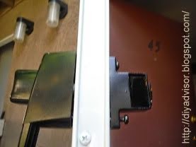
Step 7: Fig.10 and fig.11 shows the final adjustment to the door screen handle.
Fig.10 Fine tuning
Fig.11 Outside handle
Step 8: Fig.12 shows the door handle latch template and fig.13 shows the template will be placed on the door frame for the exact location of the door latch.
Fig.12 Paper template
Fig.13 Template on wood frame
Step 9: Fig.14 shows the last screw being placed on the bottom of the door latch.
Fig.14 Latch done
Step 10: Fig.15 shows the door closer plans and fig.16 shows the actual parts on the door closer is attached to the door frame.
Fig.15 Door closer plans
Fig.16 Door closer
Step 11: Fig.17 shows the door screen is completely installed.
This job is done and Mr. Gonzales can invite his family for the holidays.
Fig.17 Job done
 How To Install a Custom White Aluminum Door:

Update: DIY Advisor has New blogs check them today:
  • Cookie Alert: European Union laws requires that you know that this blog uses cookies. If you are concerned about this please click here to see how Google uses this information.


Note: The DIY Advisor assumes no liability for omissions, errors or the outcome of any jobs. The reader must always exercise reasonable caution, follow current codes and regulations that may apply, and is urged to consult with a licensed contractor if in doubt about any steps on these posts. All names were changed to protect client's privacy. DIY Advisor. Reproduction of site content including photos without permission prohibited. All rights reserved. © Copyright 2011-

Sunday, March 1, 2015

How to Replace Fiberglass and Drywall Near a Water Heater

The drywall knives
By Gary Boutin  
Helpers: Carl N. and David V.               

Supplies and Tools: 
Cordless drills 12 volt and 18 volt 
Drywall knives
Drywall screws - coarse
Electrical plates
Fiberglass rolls R19 
Hammer claw with rubber grip
Hammer staple with extra staples
Mud pan
Joint compound
Paper tape
Paint cans 
Sanding screens
Tool belts  

Mrs. Stone wanted her garage walls repaired. She had the city place a new water heater in her garage, and each step needed to be inspected. The water heater had to replace and fiberglass needed to be installed in the walls. There were three area that needed to be inspected. He needed to inspected the installation of the fiberglass, the installation of  the new sheetrock around the water heater and finely the painting of the garage walls. The painting was going to be done by another contractor.

This post shows the nine steps to replace fiberglass ans drywall  by the water heater. Now the home owner was able to get insurance for the garage.

Step 1: Fig.1 shows the new fiberglass rolls R-19 purchased at a warehouse store. Including supplies coarse drywall screws, paper tape, 1/2 inch drywalljoint compound and sanding screens.
Fig.1 Garage fiberglass rolls

Step 2: Fig.2 through fig.8 shows the walls were inspected and repaired of any small wall damage. This includes removing all the nails and staples from the wood studs. This was done to have a smooth surface when the new sheetrock was placed on the wall studs.
Fig.2 Removing nails

Fig.3 Heater wall repair
Step 3: Fig.4 through fig.8 shows Carl placing several metal plates were needed to cover the electrical wires and or water pipes. Some area were sprayed with paint.  
Claw hammer used to remove large nails

Fig.5 Checking existing fiberglass
Fig.6 Carl checking ABS drains pipping
Fig.7 Removing 16D stud nails
Fig.8 Finishing simple repair
Step 4: Fig.9 and fig.10 shows that the installation of the fiberglass into the walls that have no existing fiberglass and staple the edges to the wood studs. Some of the existing fiberglass was too damaged and needed new fiberglass added to the wall.
Fig.9 Fiberglass by water heater

Fig.10 By water heater
Step 5: Fig.11 through fig.12 shows the metal plates are hammered into the studs that protect the electrical wiring inside the wall. The electrical plate prevents a nail or screw from getting herself into any live electrical wiring, or water, drain pipes.
Fig.11 Fiberglass in wall

Fig.12 Adding electrical metal plates

Step 6: Fig.13 shows that some parts of the wall have large ABS pipes in them and its important to know were they are but not put in a screw into the pipe.
Fig.13 Electrical plates


Step 7: Fig.14 through fig.15 shows Carl and David installing wallboard over the new fiberglass. Some of the wallboard are large pieces and some are small pieces. It's like a jigsaw puzzle that both Carl and David had to solve.  
Fig.14 Repair water heater wall

Fig.15 David and Carl work on wall

Step 8: Fig.16 through fig.17 shows Carl doing some special measurements for drywall behind the water heater. Some pieces like fig.18 needed to be measured and cut to fit around the water piping.
Fig.16 Carl at water heater
Fig.17 Carl measuring area around water heater
Fig.18 Custom water heater piece


Step 9: Fig.19 through fig.21 show the wall pieces have their first coat of drywall joint compound. And now the job finished.
Fig.19 Joint compound dried
Fig.20 New wall piece added to wall
Fig.21


Update: DIY Advisor has New blogs check them today:
  • Cookie Alert: European Union laws requires that you know that this blog uses cookies. If you are concerned about this please click here to see how Google uses this information.

Note: The DIY Advisor assumes no liability for omissions, errors or the outcome of any jobs. The reader must always exercise reasonable caution, follow current codes and regulations that may apply, and is urged to consult with a licensed contractor if in doubt about any steps on these posts. All names were changed to protect client's privacy. DIY Advisor. Reproduction of site content including photos without permission prohibited. All rights reserved. © Copyright 2011-