|
| Fig.1 Hex head screws |
By Gary Boutin
Supplies and Tools:
GE WCRE6270 owner's manual
Hex head screwdriver 1/4 inch (3)
Lid switch kit WH12X1033
Ruler for the 1/8 for of an inch
Schematic diagrams and Directions
This post shows the thirteen steps to removing the control panel from washer mother board and reading the schematic direction on how to remove the metal cabinet around the General Electric washer.
Step 1: Fig.1 shows one of the 3-hex head screws that will need to be removed with a hex head screwdriver from the upper top back side on the control panel. The instruction state there are four hex head but my model only had three hex head screws that were at the very top of the back of the control panel.
Step 2: Fig.2 shows a 1/4 inch hex head screwdriver.
 |
| Fig.2 Hex head screwdriver |
Step 3: Fig.3 shows that the control panel must be lifted up slightly off by sliding it to the left. There are three tabs that attach the control panel. That the one with all the buttons. Slide the top sleeve out from under the control panel about 1/8 of an inch.
On this model you have to balance the washer top piece, these tabs can
be easily break they are made of plastic. The entire top will move but
its connected by a hose so be careful.
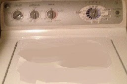 |
Fig.3 Control panel
with all the buttons |
Step 4: Before removing each terminal, place
tape near each terminal and on the terminal wiring to make sure that
each terminal is placed in the correct order. Turns out each terminal
was very different from each other and this step could have been
skipped. Fig.4 shows terminal #1, fig.5 shows terminal #2 and fig.6 shows black terminal. Remove
all three control harnesses from the wiring harness to partly release
the metal panel. The metal panel is still hooked by a rubber hose. The hose determines the water amount in the washer. Do
not disconnect the hose. The panel must be balanced between the top
washer.
 |
| Fig.4 #1 Terminal |
 |
| Fig.5 #2 Solid white terminal |
 |
| Fig.6 #3 Dark blue terminal |
Step 5: Fig.7, fig.8 and fig.9 shows how each terminal wire was marked with paper tape and a number was applied to it.
 |
| Fig.7 #1 |
 |
| Fig.8 #2 |
 |
| Fig.9 #3 |
Step 6: Fig.10 shows the washer mother board with terminal being removed to prevent any short circuits.
 |
| Fig.10 Disengaged control panel |
Step 7: Fig.11 shows the schematic diagrams
for this washer and complete installation guide with pictures on how to
replace each part of the washer for the repair technician. Each model comes with its own specific
page and that is why each page has a unique serial number. Fig.12 shows the schematic and direction serial number.
 |
| Fig.11 Schematic diagram |
 |
| Fig.12 right side serial number |
Step 8: Fig.13 #1 shows directions to remove the control panel.
 |
| Fig.13 Directions |
Step 9: Fig.14 #3 shows how to remove the Front Panel.
 |
| Fig.14 Front Panel |
Step 10: Fig.15 #4 shows how to remove the front panel. You can tell the washer has a front panel when you look at the sides of the front washer. The washer front panel will have a seam.
 |
| Fig.15 How to removed top panel |
Step 11: Fig.16 #4 shows how to
Remove a Cover/Lid Assembly.
 |
| Fig.16 Remove a Cover/Lid Assembly |
Step 12: Fig.17 shows an importance notice. Important Reconnect All Grounded Devices.
 |
| Fig.17 Grounded Devices |
Step 13: Fig.18 shows the schematic diagram. These directions are not on the Internet you have to have gone to appliance school to slowly pick up these schematics and direction sheets. I have searched the Internet and I have only found parts schematics with part numbers. These are better because they show everything on how to repair the washing machine.
 |
| Fig.18 Schematic diagram. |
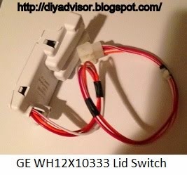
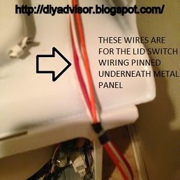
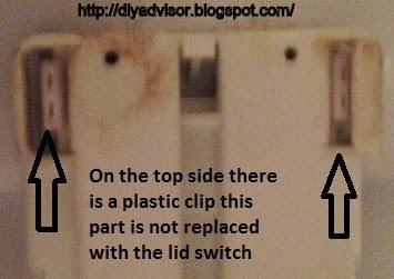
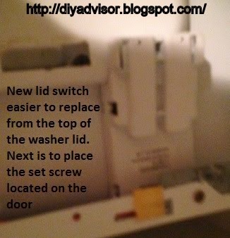
General Electric Washer Lid Switch Assembly:
Update: DIY Advisor has New blogs check them today:
- Cookie Alert: European Union laws requires that you know that this blog uses cookies. If you are concerned about this please click here to see how Google uses this information.
Note: The DIY Advisor assumes no liability for omissions, errors or the outcome of any jobs. The
reader must always exercise reasonable caution, follow Current codes and regulations that may apply, and is urged to consult with a licensed contractor if in doubt about any steps on these posts. All names were changed to protect client's privacy. DIY Advisor. Reproduction of site content including photos without permission prohibited. All rights reserved. © Copyright 2011-